A Guide to Photogrammetry Photography
Published May 1, 2020
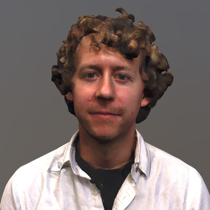
Humans perceive and experience the world in three dimensions. Photogrammetry provides a bridge from the physical world’s reality to digital immersive realities.
It enables journalists and storytellers to digitize pieces of the physical world for creating immersive and experiential stories that are three-dimensional, and native to the human’s three-dimensional perception. Audiences can now step into a story, interacting with story-significant objects and environments in ways not possible with two-dimensional videos and photos.
![]() Download this GuideThe photogrammetry process dates back to 1849 and Aimé Laussedat, who used the technique for creating topographic maps. Photogrammetry has largely been the domain of surveying, archaeology, mining and other industries relying on geospatial data and analysis. With the abrupt rise of immersive media tools and platforms in 2015, photogrammetry began receiving increased attention from journalists and other digital media creatives interested in producing digitized clones of static real world objects, environments, structures, and landscapes for 3D immersive media environments and storytelling, without the need for computer generated interpretations and 3D modeling.
Download this GuideThe photogrammetry process dates back to 1849 and Aimé Laussedat, who used the technique for creating topographic maps. Photogrammetry has largely been the domain of surveying, archaeology, mining and other industries relying on geospatial data and analysis. With the abrupt rise of immersive media tools and platforms in 2015, photogrammetry began receiving increased attention from journalists and other digital media creatives interested in producing digitized clones of static real world objects, environments, structures, and landscapes for 3D immersive media environments and storytelling, without the need for computer generated interpretations and 3D modeling.
Examples of immersive media and journalism using photogrammetry:
- TIME’s Inside the Amazon: The Dying Forest AR experience
- The ruins of the Ukraine’s Donetsk Int’l Airport Terminal, a 2015 example of journalistic drone photogrammetry on Sketchfab by Matthew Schroyer
- The VR experiences Greenland Melting and After Solitary by Emblematic Group and PBS FRONTLINE
- JOVRNALISM’s Homeless Realities AR story on Snapchat
- Work by the McClatchy New Ventures Lab and McClatchy journalists (on Sketchfab and the McClatchy Actual Reality app)
- Three-dimensional models embedded in stories by PBS NewsHour, a 2018 Journalism 360 grant winner: Explore the haunting remains of an Antarctic whaling boomtown and This sculptor builds what’s going on inside our heads
- The Yahoo News AR story Rebuilding Paradise, viewable in the Yahoo News app
- The New York Times’ Augmented Reality: David Bowie in Three Dimensions, and A Volcano Turns a Town Into a Cemetery
- Quartz’s The 2050 Project
- The BBC’s Explore the IS tunnels story and for content in the Civilisations AR app
- The Guardian’s VR story Limbo
- USA Today’s The Wall VR experience
- A reconstruction of Nairobi’s Dandora Dumpsite and other projects by me, Ben Kreimer
Table of Contents
- How to Use This Guide
- Basic Equipment
- The Capture Process
- Visualizing all the Photos Together
- Large Scale and Drone-Based Photogrammetry
- Capturing a Room Interior
- Photogrammetry Capture Guidelines to Remember
- Ring Flash Photography
- Shooting Underneath Objects
- Processing Your Images
How to Use This Guide
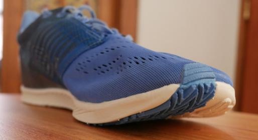
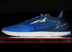
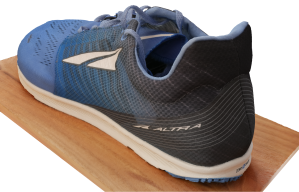 Photogrammetry involves capturing multiple images of an object, structure, or landscape, with overlap, and from different perspectives. Photogrammetry software designed for processing these image sets is then used to produce three-dimensional models of structures, landscapes, objects (like the 3D shoe on the right) and two-dimensional aerial imagery.
So you can follow along, this guide has been designed to show how to apply the photogrammetry photography process to common objects, structures and landscapes, demonstrating what works, why it works, and what doesn’t work, and why it doesn’t work. Included are advanced tips on how to use plexiglass for capturing all surfaces of an object, and how to incorporate a ring flash as a portable and powerful light source.
Note: This guide will not take you through software workflows because there are many different pieces of photogrammetry software available. There are other tutorials already available for the software of your choice.
Basic Equipment
Camera
Any digital camera or mobile device will work, but the larger the camera sensor the easier it is to produce a high quality photogrammetric reconstruction, as explained below.
Measuring tape (optional, but recommended)
A measuring tape is for taking a distance measurement (or two) from the subject object or environment. This reference distance is fed into photogrammetry software, resulting in a properly scaled model. If you don’t provide your photogrammetry software and the 3D reconstruction with a known distance from the subject, the scale of the 3D model will be completely arbitrary.
For example, a human’s 3D reconstructed shoe will look correct as a model, but if you don’t tell your software the shoe’s actual scale once you put it into an augmented reality or virtual reality environment it may be the size of a car. Scaling models becomes increasingly important when you bring multiple photogrammetric objects together into the same immersive environment.
Choosing your Camera
Every camera has an image sensor that acts like a net for catching light, and the more light you catch the better. Large cameras, like DSLRs, with large image sensors (not necessarily more megapixels) collect more light and yield better results than cameras with small image sensors, like those found in mobile devices. Large camera sensors are better for photogrammetry, especially in non-sunlight environments, because when you shoot with a high f/stop (small aperture) lens setting that ensures your entire frame is in focus you’ll also have less light reaching your sensor than at lower f/stops (large aperture) settings. Slowing the shutter speed and increasing the ISO will help your camera utilize the limited light that is available, but together they can only do so much. Slow shutter speeds can cause motion blur if a tripod isn’s used, and high ISO settings can cause digital noise appearing as off-color pixels that also hinders photogrammetry software.
Image quality is also impacted by sensor size. When looking at the same scene captured by a smartphone camera and a larger sensor camera, the image quality will look similar or the same if you don’t zoom in. But zoom in on both frames, and you’ll see how the image produced by the larger sensor has more detail. This additional detail provided by the larger sensor is useful to your photogrammetry software.
Don’t limit your attention to the megapixel count, as it alone is not a reliable figure for determining image quality (for more information, do a web search for “megapixel myth”).
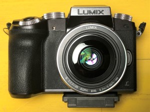
For the examples in this guide I used a Lumix G7, a 16 megapixel micro 4/3 (17.3 x 13 mm sensor ) mirrorless camera.
Getting the Most from a Mobile Device Camera
In practice, you can compensate for a small sensor camera, like a mobile device, by capturing images of the subject from close up, (never use a digital zoom because of the digital artifacts it produces). Good lighting is also very helpful.
If you’re capturing smaller objects, say a shoe, the output quality difference between a mobile phone and DSLR will be less than if you’re photographing a room. This is because it’s easy to take closeup pictures of the shoe no matter what camera you’re using, but a room is large, and there isn’t time to take thousands of pictures with a mobile device, thus a DSLR with its larger sensor is going to produce better results with fewer images.
Selecting a Camera Lens
When using a camera with interchangeable lenses, an approximately 25mm focal length (35mm lens equivalent) works well for exterior structure walls and interior spaces, like rooms, and an approximately 50mm focal length (35mm equivalent) works well for objects.
My go-to photogrammetry lens is right in the middle of that spread: a 40mm prime lens (35mm equivalent) for objects, and a 28mm (35mm equivalent) prime lens for rooms and large structures, like a house. It’s best to avoid ultra-wide lenses “below about 22mm (35mm equivalent lens),” say Phil Sapirstein and Sarah Murray in their comprehensive photogrammetry article, Establishing Best Practices for Photogrammetric Recording During Archaeological Fieldwork (available free online).
Ultra-wide lenses cause distortion, particularly around the edges of the image. Photogrammetry software can successfully remove much of the distortion from photographs captured by ultra-wide angle lenses, such as on a GoPro, with the exception of around an image’s edges.
Zoom lenses work great, for most applications, unless you’re doing ultra-high precision work, in which case a prime lens is a must. In short, if you’re doing an archaeological photogrammetry survey where millimeter precision is needed for reconstructions that will be used for taking measurements, use a prime lens. If you’re doing photogrammetry in the field that won’t be measured later, use a zoom or prime lens.
For more technical information about camera and lens selection, including the pros and cons of zoom lenses, I recommend reading Sapirstein and Murray’s Establishing Best Practices for Photogrammetric Recording During Archaeological Fieldwork article, available for free online.
How Photogrammetry Works
Managing Capture and Results Expectations
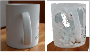
Ceramic mug (on Sketchfab)
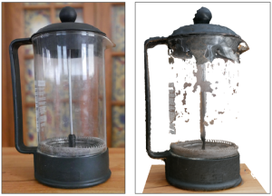
French Press (on Sketchfab)
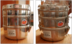
Tiffin (on Sketchfab)
Before planning a photogrammetry shoot, let alone shooting, consider the physical characteristics of the subject, and the likelihood of a successful photogrammetric result. Photogrammetry software does best with rough, multi-colored, and organic surfaces. Smooth, featureless surfaces are likely to result in holes or deformities. Examples below show objects and materials below that photogrammetry softwares struggles to reconstruct, including a white ceramic coffee mug, a french press made of black plastic and glass, and a stainless steel tiffin.
Difficult or impossible to reconstruct materials include:
- Shiny and/or smooth materials (transparent glass, single color plastics, shiny metals, etc.)
- Single color materials lacking a physical texture (a blank piece of paper, or white wall)
- Transparent glass surfaces
- Mirrors
What Photogrammetry Software Sees
Photogrammetry images are meant for computer and photogrammetric software rather than human eyes. Common photography rules and techniques meant to enhance an image for human eyes, including the rule of thirds and shallow depth of field, hinder photogrammetry software’s ability to process imagery.
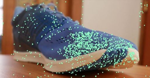
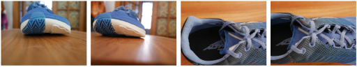
Such software needs evenly exposed and deep depth of field images captured using a high f/stop value so the entire frame, or as much of the frame as possible, is in focus. This maximizes photogrammetry software’s ability to automatically identify, tie points, or uniquely identifiable reference points that the software has recognized in at least two photographs. You need tie points for the software to successfully reconstruct what you’ve photographed. For example, shallow depth of field is appealing to the human eye in the left image, but has reduced the number of tie points the software can identify, as seen by the dearth of green tie point dots at the out-of-focus back of the shoe in the right image.
The rule of thirds doesn’t apply in photogrammetry. Instead, fill the frame with your subject, as with the house and garage example in the image sequence below, with enough overlap from image to image, about 70%-80% on the sides and top and bottom of the frame. Or if your subject is smaller, like with the shoe sequence below, center your subject in the frame, capturing it from many different perspectives.
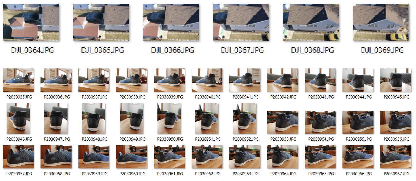
You know you’re capturing adequate overlap and perspectives when scrolling through the images in your camera is like going through a flipbook, with each image flowing into the next. Always overshoot your subject. It’s easier to remove photos for processing than it is to go back and reshoot. If you don’t capture enough images with enough overlap from image to image, and if those images don’t show your subject from every angle, your reconstruction will have holes and pixelated areas, or it could fail altogether. If the software fails to understand how the images fit together, the process fails.
The Capture Process
Camera Settings
- Disable in-camera stabilization, as this can hinder the photogrammetry processing algorithms.
- Find a balance between f/stop, shutter speed, and ISO settings:
- Use aperture priority or the manual setting, and set your f/stop so the entire frame is in focus. Don’t set and forget this setting, as it will change based on your lens and the distance between your camera and your subject matter.
- Ensure your shutter speed is adequate for the lighting conditions and how you will move the camera.
- Handheld: If you’re going to capture photos without a tripod, a common practice, set a higher shutter speed of at least 1/200 or faster (or slower if you’re steady with the camera).
- If you’re using a tripod you can set a very slow shutter, ideal for revealing surfaces in darker environments, but severely slows down the capture process, and limiting camera placement and the perspectives you can capture.
- Set your ISO setting so that your photographs of the subject matter are not underexposed. You want to keep the ISO as low as possible so as not to produce digital artifacts in your images. Some trial and error with your camera will indicate where this threshold is. If you’re seeing artifacts, noticeable as dark off-color noise in the image, lower the f/stop so that you can achieve an acceptable ISO setting, or shoot with more light.
- Remember: Cameras with larger sensors are more forgiving and create fewer artifacts than cameras with smaller sensors. Cameras with larger sensors also collect more light, lessening your need to increase the ISO. ISO induced artifacts are very bad for photogrammetry because the artifacts obscure the subject matter at the pixel level, decreasing the software’s ability to find identifiable points and reducing the overall quality of your 3D reconstruction.
Tripods
Tripods are useful when ambient lighting is poor and you need to do long exposures to make it possible to shoot with high f/stop values. A tripod is also needed for using HDR modes to prevent movement between the capture of each component frame. I try to avoid using a tripod because it can severely limit your camera placement, which can limit the range of subject perspectives you can photograph. Instead, I prefer a ring flash (see the Ring Flash Photography section for more information).
Your Subject Cannot Move
To have a successful photogrammetric reconstruction, your subject cannot move at all during the capture process. Movement will result in a partially or completely failed reconstruction because the software relies on identifiable points that remain in the same position from photo to photo. Movement will cause distortions in the reconstruction process, or outright failure.
The photogrammetry software will identify tens of thousands of identifiable points per photograph, eventually matching up those points with the same identifiable points present in other photographs. This includes the presence or movement of shadows.
The only occasion when it’s okay to move the subject is when you’re doing turntable-based photogrammetry where your subject matter, using a small insect or other small object, is on a rotating mechanism surrounded by a white background. In this setup, the camera remains motionless on a tripod, while the subject matter rotates on a vertical axis, and ideally the axis is tilted to expose the bottom and top surfaces to the camera.
Shadows
 Shadows become a part of your 3D reconstruction. If you set your camera’s exposure to properly capture the brighter surface then the darker surface may reconstruct with holes or digital artifacts due to inadequate lighting where the photogrammetry software fails to identify enough tie points. Late afternoon and evening is a difficult time to shoot photogrammetric images outside because of the fading light and long shadows. When sun-generated shadows are involved, do your photography when the sun is highest in the sky or on an overcast day to minimize shadows, and work as quickly as possible to capture your photoset to minimize shadow movement. HDR photography is a solution, but only if the camera remains motionless during the multiple exposure capture process.
Capture Three Layers of Images
Remember: Always center your subject and fill most of the frame or use 70-80% overlap when the subject extends beyond the boundaries of the frame.
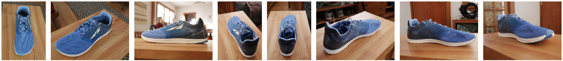
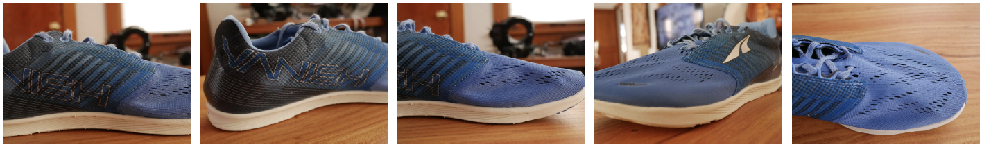
Context Shots: Capture the entire subject, or most of the subject in the frame from about 8-10 different perspectives. This is as far away from the subject that you will be during the shoot, as shown with the shoe. These images will give the software context for the closeup shots that will provide the detail.
Closeup Shots: Get as close to the object as you can while considering the time it will take to capture the entire subject, and the total number of pictures that you can process. These images will reveal the details of your subject.
Midrange Shots: Depending on the complexity of your subject and its size, shoot a series of photos at about half the distance between your context shots and closeup shots. These images will ensure you’ve thoroughly photographed your subject, and that the photogrammetry software will understand the relationship between your closeup shots and context shots.
Visualizing the Photos All Together
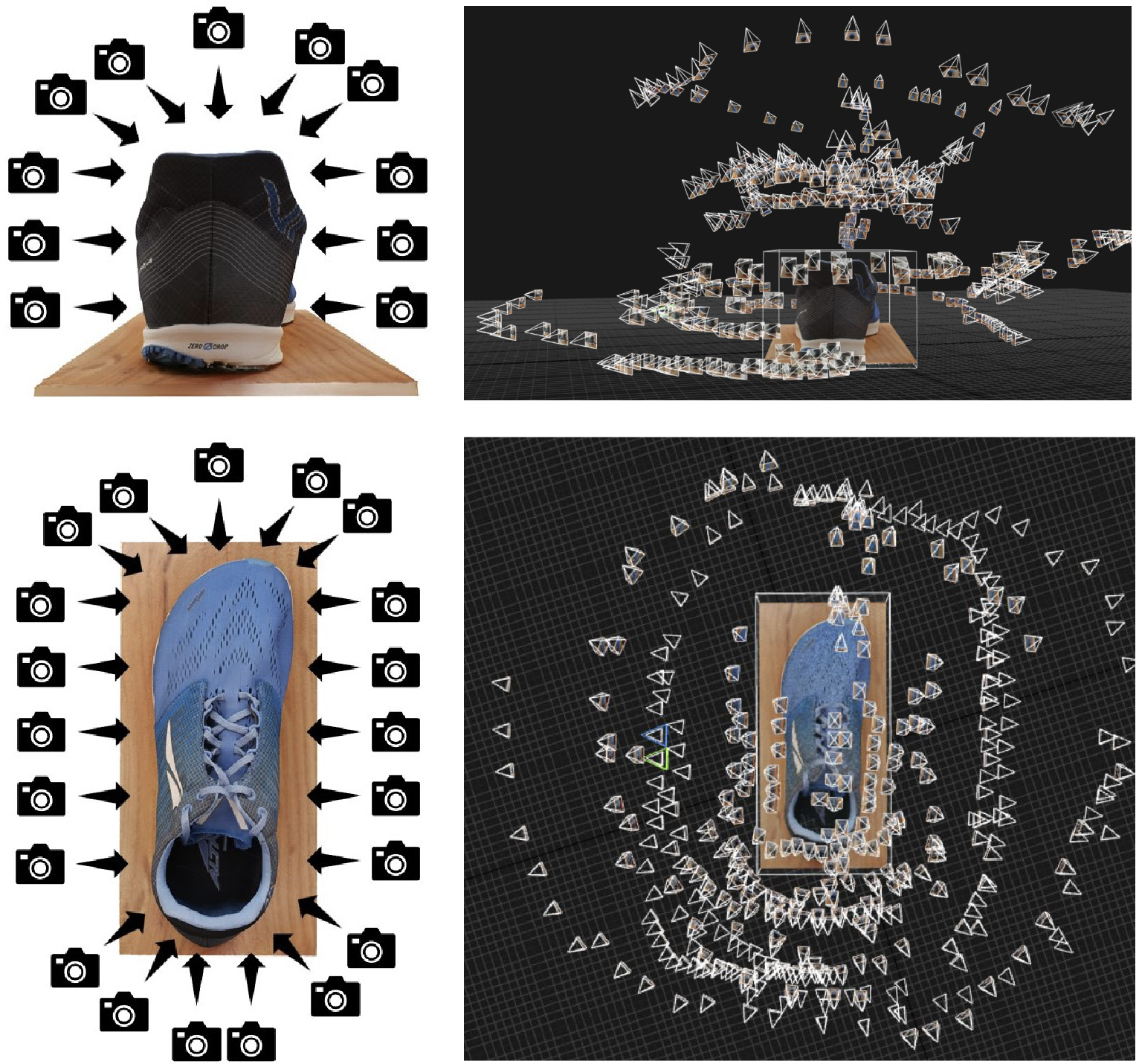
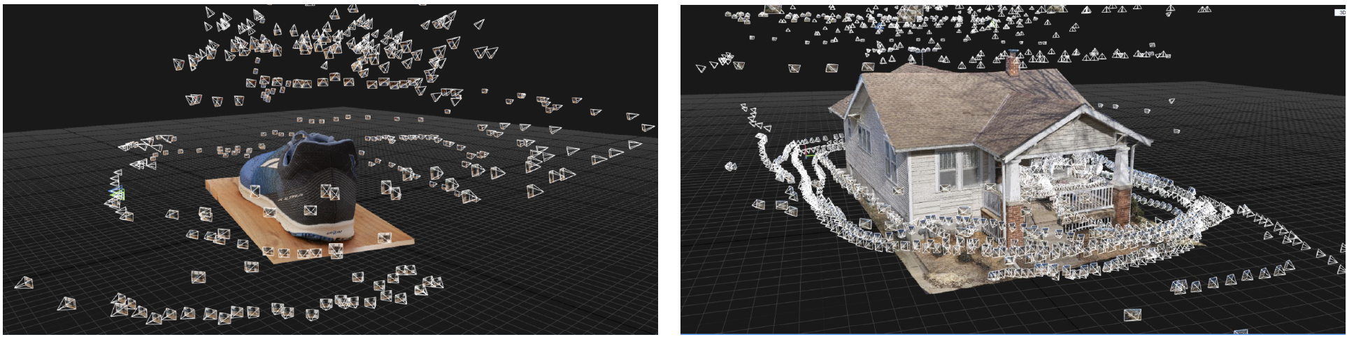
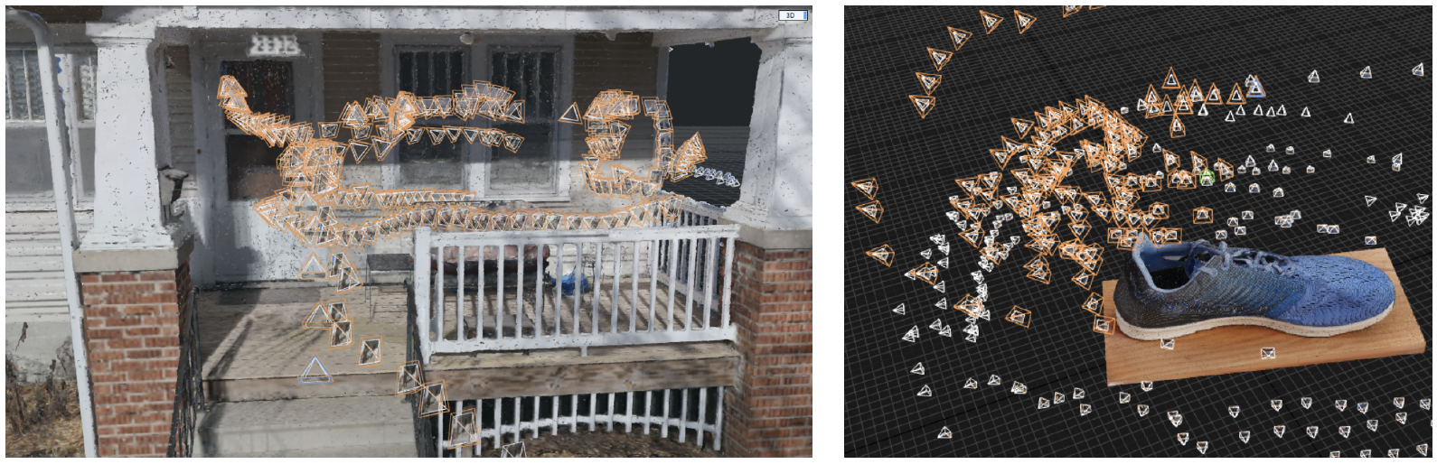
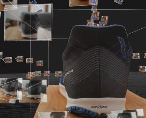 The following graphics show image capture positions around the shoe. Below on the left are basic guides showing the camera movements around the shoe, along with screen grabs from Reality Capture, my preferred photogrammetry processing software, showing the 3D reconstruction of the shoe, and the actual image positions for each of the 393 images captured for this reconstruction.
The screen grab images show the same shoe reconstruction but from two perspectives: one looking down at the top shoe and the other looking at the rear of the shoe. Each pyramid represents a photograph in 3D space around the shoe, as shown by the closeup image on the right. Looking at the shoe’s image positions from the back and the top, notice the layers and density of images, as described above in the layering section.
Photogrammetry photography of any object, whether it’s a shoe or the exterior of a house, will be captured in this manner, with photos looking inwards at the object, and from all perspectives around the object.
Taking a Measurement
I carry a measuring tape to photogrammetry shoots. After taking photos I take a measurement between two easily identifiable points on the photogrammetry subject. I take a picture of the measured points using my iPhone, writing the distance measurement onto the image. Ensure that the points you take a measurement from are visible in many different photos you took. Using the shoe (men’s size 10.5) as an example, I took a measurement from the corner base of the ‘F’ to the corner end of the lowest line on the ‘E’ as indicated on the next page.
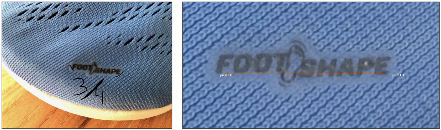
This distance is entered into the photogrammetry software using control points. As an alternative, before you take photogrammetry photos of your subject, you can place a ruler, measuring tape, or an object of known length next to your subject. When processing the image in photogrammetry software set you can place distance control points on the measuring device to scale the reconstruction, later cropping out the device from the reconstruction.
Why Measurement-Based Scaling is Important
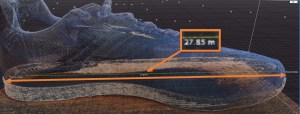 When processing the images without a defined measurement, Reality Capture arbitrarily scaled the shoe so that it was 27.85 meters in length, or over 91 feet. That’s a giant shoe! This is shown below in the screen grab image from Reality Capture, showing the shoe as a point cloud, and including the distance from the front of the shoe to the back, as shown by the yellow line (the orange lines and graphic have been added for clarity).
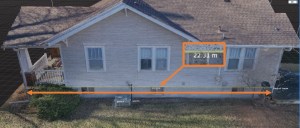
To further illustrate the importance of measuring, here’s a photogrammetrically reconstructed house. Without providing a known distance measurement, Reality Capture has scaled the house so that it’s 22.31 meters in length, or just over 73 feet, making it smaller than our photogrammetric shoe.
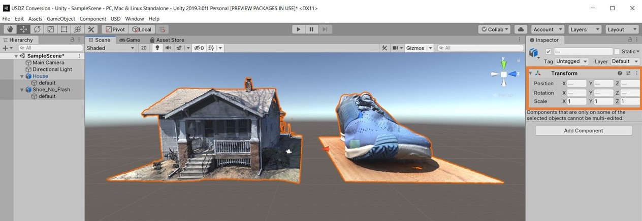
 When importing these two models into Unity for creating a virtual reality or augmented reality scene, the scale problem becomes very apparent when the shoe is as big as the house. This shows why providing known measurements during photogrammetric reconstruction is important, especially when working with multiple objects. Even if you had two identical objects, your photogrammetry software might scale them differently, unless you provide a defined measurement.
The Finished Shoe
Here’s the finished 3D model of my shoe, viewable on Sketchfab. In the next section I will show you how to improve this type of photogrammetric capture, or the capture of any object, by also photographing its underside.
Capturing a Room Interior
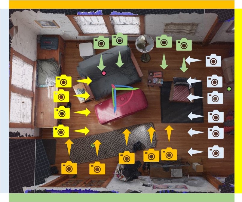
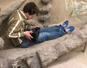
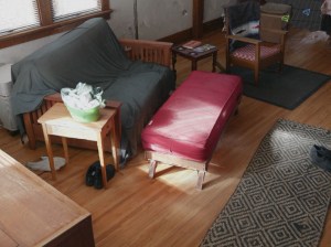 Object capture, no matter the scale, involves taking photos that are facing inwards, towards the subject matter. To reconstruct a room as I’ve done in the image on the right (see it on Sketchfab), the photography capture process is similar, but the subject focus isn’t just in the middle of the capture space, it’s also what resides on the opposing wall. For example, in the graphic below, the colored cameras and arrows correspond to their opposing walls. Each grouping of images with the same orientations is capturing the furniture in the middle of the room, and the wall on the opposite side of the room. In addition to capturing the room with opposing photographs as shown in the graphic, many additional photos are needed to adequately capture the individual objects located through the space.
Capturing a room in a house can be difficult because of inconsistent lighting and challenging surfaces, including glass and featureless white walls, which can reconstruct poorly and dynamic lighting. Such reconstructions are likely to need cleanup work after the photogrammetry reconstruction.
Large Scale and Drone-Based Photogrammetry
Whether you are doing photogrammetry of a shoe or a house, the process is the same, but the tools differ. Notice the image positions above and all around the shoe and the house. A handheld camera was used for both photogrammetry shoots.
I walked around the house with my camera using a 28mm (35mm equivalent) lens taking overlapping photos as I walked (the shutter speed was fast).
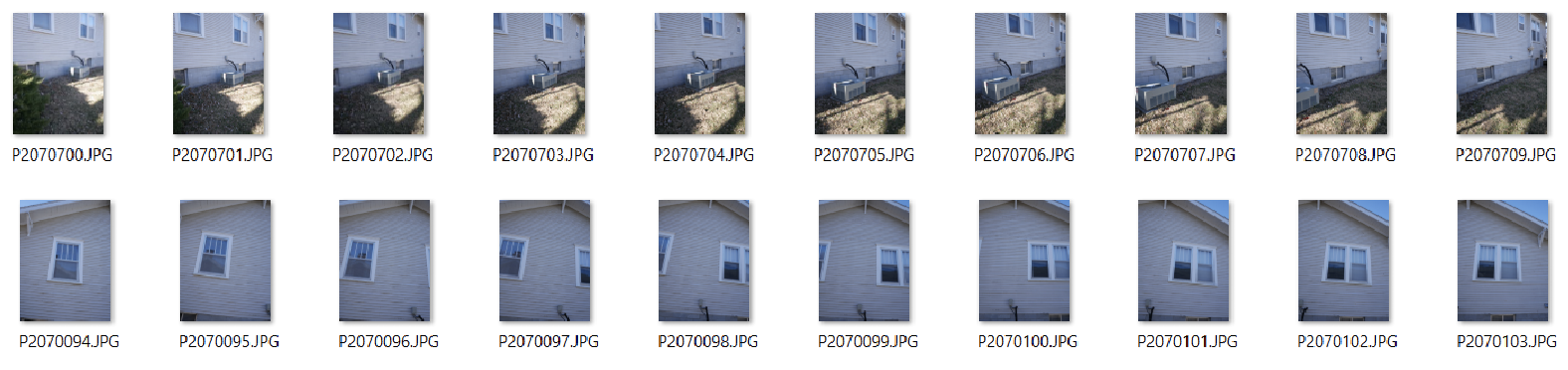
Unlike the flat sides of the house or sides of the shoe, the front porch and tongue and foot pocket of the shoe have multiple layers of overlapping faces, and require additional photographs to capture their intricacies. The highlighted orange photos in the following images show the density of images in these complicated areas.
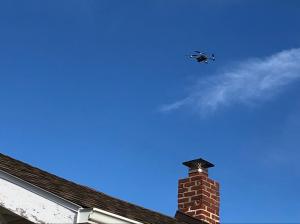
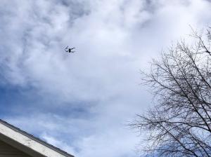
A DJI Mavic Pro 2 drone was to capture the roof and the sides of the house from a downward facing perspective.
If you know how to reconstruct a shoe you know how to reconstruct a house. The only difference is their size, and the need for a flying camera (a drone) to capture the roof of the house.

It took about 80 minutes to capture the 1900 images that went into the house 3D reconstruction, as seen below.
Autonomous Flying for Working Faster
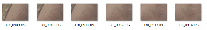
It can be useful to prepare an autonomous flight path for the drone to follow so that you don’t have to keep track of what you’ve photographed. If a landscape has few identifying characteristics, like a sandy beach or grass field, it becomes very difficult to track where you’ve flown. There are many mobile apps available for doing aerial photogrammetry. Because I fly DJI drones, I use the free DJI GS Pro app.
Before Flying Autonomously
- Plot the flight area of your aerial photogrammetry by first flying the drone to determine the flight boundaries. By doing this you’re figuring out where the drone needs to fly to completely capture your subject, and how close you can get to obstacles to avoid collisions.
- When facing adjacent obstacles, give yourself plenty of clearance space for wind and GPS inaccuracies that could cause your drone to drift off course. The more space you have between your drone and the obstacle the more time you have to stop a collision.
- Similarly, identify the tallest obstacle underneath your drone flight area, fly to that object, note the above ground altitude height in your drone’s app, and then set the transects altitude to sit at least six feet higher in altitude.
Remember: Regardless of the flight conditions and plan, always keep your drone within eyesight, paying close attention to nearby obstacles.
Transect Settings
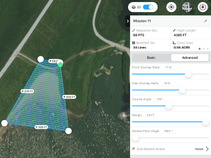 Transects are the zig-zagging line paths that the drone will follow while capturing photos. When on-site it’s always better to overshoot, so plan on a transect overlap and sidelap setting of 70-85%. If you’re photographing a structure, use 85% overlap and sidelap. If you’re capturing a landscape, like a field, 70% overlap and sidelap will suffice, but 80% won’t hurt, unless you’re trying to conserve battery power for longer flight times and greater terrain coverage.
After considering your overlap and sidelap needs, set your altitude, and take note of the estimated flight time. Always fly as low as possible, while considering the flight time, battery life, and time you have on location. The higher you fly the faster you fly, enabling you to cover more ground but at the cost of lower per pixel resolution because the camera is further from the surface that you’re capturing.
Gimbal and Camera Pitch Angle Settings
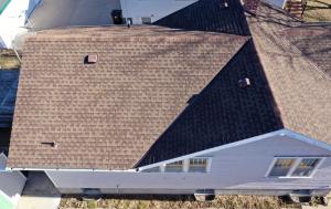
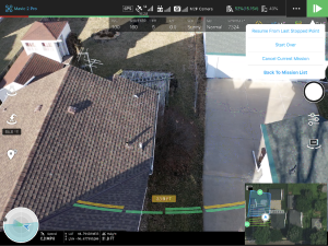 In the above mission I’m photographing a sandy beach beside a lake with a camera gimbal pitch angle of -90 degrees, indicating that the camera will point straight down at the ground. The terrain has a gentle slope with no significant vertical features, like buildings or rock faces. In contrast to the beach, in the mission below, the drone is capturing a house with surfaces of various angles, including a pitched roof and vertical walls. To capture all of these surfaces, especially the vertical walls, you must fly oblique angles of about -45° to -60° as the camera is doing below. If the camera is set at -90° the resulting images will lack surface definition of the vertical wall surfaces.
Using Drone Photogrammetry for Mapping in Google Earth Studio
 In addition to 3D models, photogrammetry software can also produce orthorectified imagery of a reconstructed object, structure, or landscape. The orthorectification process removes all surface relief and image perspective from camera tilt, resulting in uniformly scaled imager. Satellite imagery, as seen in Google Maps, is an example of orthorectified photography.
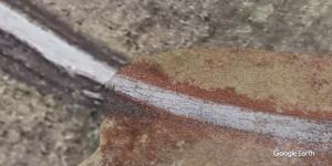
Drone-based orthorectified aerial imagery can serve as a significantly higher resolution alternative to satellite photography. In addition to providing higher resolution imagery than what is available to civilians from satellite-based imagery, drone-based orthorectified imagery can be created on-demand, immediately after a storm for example, without waiting for satellite-based camera obscuring waiting clouds to disappear, and without going through the process of gaining access to the imagery. The image below shows the quality difference between satellite imagery in Google Earth Studio with my orthorectified drone imagery.
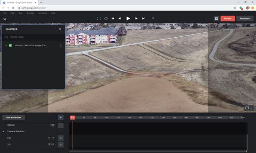
To produce a map for use in Google Earth Studio (and Google Earth Pro) or elsewhere, follow the same photogrammetry photography process presented above. The basic principle of flying transects with 70-85% overlap remains the same. The only difference in procedure occurs after you have captured your photographs and have processed the imagery in your photogrammetry software. Instead of exporting a 3D model you will export an orthorectified image. Export a KML version of your orthoprojection and import the KML file package into Google Earth for overlaying atop the platform’s pre-existing topography, as seen below.
Photogrammetry Capture Guidelines to Remember
- Take photographs of your subject object, landscape, or structure with about 70-80% overlap from photo to photo. Looking through your captured photographs should look like watching images in a flipbook.
- The following surfaces are difficult or impossible to photogrammetrically reconstruct:
- Shiny and/or smooth materials (transparent glass, single color plastics, shiny metals, flat screen displays, etc.)
- Single color materials lacking a physical surface texture or relief (a blank piece of paper, a white wall)
- Transparent glass surfaces
- Mirrors
- Use a high f/stop so that the entire frame, or as much of the frame as possible, is in focus.
- Make sure your subject is well lit
- Take a measurement of your subject for properly scaling the photogrammetric reconstruction
Ring Flash Photography
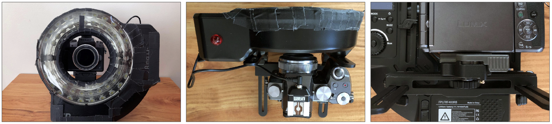
A Linear Polarized Ring Flash
 A 400 W/s ring flash battery-powered ring flash is a powerful tool for photogrammetry in situations where ambient is low, or non-existent. It’s unbeatable for quickly and evenly lighting objects. With its intensity, you can easily shoot at f/16 or higher on your camera’s lowest ISO setting. Plus it’s a very portable lightsource as opposed to lights and stands, which bring shadow challenges because the object has to be completely and evenly lit.
The ring flash is useful in many indoor environments where the ambient lighting is suitable for human eyes, but requires a camera to shoot at high ISO settings to make it possible to shoot at a high f/stop for photogrammetry. Most importantly, the portability of the ring flash enables you to quickly illuminate surfaces in hard to reach areas, as demonstrated on the right.
To maximize the utility of the ring flash, attaching a linear polarizing gel over the flash, along with a circular polarizer on the lens, will prevent the flash burst from reflecting off surfaces and appearing in your photo. This is essential for surfaces that reflect light, and makes it possible to shoot through plexiglass and glass. This polarized ring flash setup allows you to capture the undersides of objects placed on plexiglass, and when the occasion arises, to do photogrammetry photography through glass.
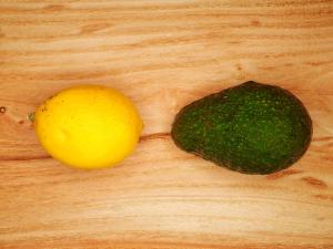
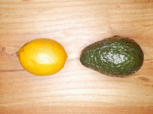
The images of a lemon, avocado, and wood surface, demonstrate the effect of polarization when using the ring flash. The image on the left was captured with the ring flash, but without the linear and circular polarizing filters. The image on the right was captured using identical settings on the camera and ring flash power setting, but with the polarization filters.
Buying a Ring Flash
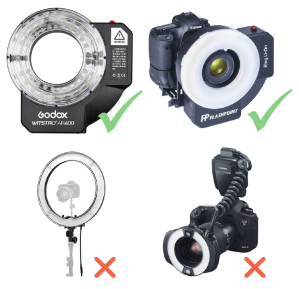 The Godox Witstro AR400 and Flashpoint Ring Li-On ring flashes (top row at right) have different labeling but both contain the same components and specifications, including a 400Ws flash bulb and LEDs. They are suitable for small to large-scale indoor object and small room capture photogrammetry. This is all the flash you need for doing indoor object photogrammetry, even if the space is pitch black. When using the Ring Li-On, I consistently shoot at 200 ISO, f/16, 1/200th of a second and get, even if the room is pitch black.
I don’t recommend other ring flash hardware, or ring lights (bottom row at right). The ring light, with it’s LED halo, is a constant light source, and provides a light glow but lacks the lighting power of a more powerful flash. The low power ring flash on the right is designed for macrophotography, and will not be suitable for non-macro imaging. The majority of ring flashes available are in this small, macro form factor, and they should be avoided, unless you’re doing macro-photogrammetry.
Linear and Circular Polarization
You cannot buy a gel holder for these ring flashes. I bought a linear polarizing sheet, cut the gel to the shape of the flash, and used gaffers tape to attach the linear polarizer filter to the ring flash. It looks rough but performs perfectly.
What you need:
- An A4-sized (approximately 8.5” x 11”) linear polarization gel that fits over the ring flash. Buy two sheets, in case you mess up the first attempt because the sheet tears easily.
- Gaffers tape
- A circular polarizer filter that fits your lens. The B+W XS-Pro Kaesemann High Transmission Circular Polarizer MRC-Nano Filter works well.
- A PC sync port adapter if your camera doesn’t have the port built in, such as a Wein Products Safe-Sync Hot Shoe to Hot Shoe adapter that has a PC sync port (pictured below in center).
- The male to male PC sync cable that comes with the ring flash.
Recommended Accessory:
- A quick release adapter with mounting plate that corresponds to the tripod make and model you use. This is essential for speeding up the attachment and removal of your camera from the ring flash mounting bracket. Without the adapter you’ll have to center your camera in the ring every time you attach it to the ring flash. Seen here at right is the Manfrotto 323 RC2 Rapid Connect Adapter with Quick Release Plate.
Shooting Underneath Objects
How to Capture the Underside Of an Object Using Plexiglass
When doing photogrammetry, you can only reconstruct the surfaces visible to your camera during image capture. If for example the demonstration shoe is on a wood table, the bottom of the shoe is not visible, and if you move the shoe to capture the bottom the reconstruction will fail.
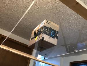
Transparent acrylic-based plexiglass, like that used in museum exhibits and aquariums, functions as an invisible support surface for photogrammetric captures, allowing you to photograph all sides of an object from above and below the object. Unlike glass, plexiglass can support significantly more weight than glass without breaking, easily a few pounds, but approach this technique with caution and common sense. This plexiglass technique was used to produce the 3D model of the shoe with its sole, as seen at right (on Sketchfab).
 What you Need:
- ¼” or thicker transparent acrylic plexiglass sheet (available at home improvement stores and Amazon). Acrylic sheets can support significantly more weight than an equivalent-sized glass pane.
- Sizing your sheet: The overall dimensions are based on the object it needs to support. The sheet must be large enough so your object sits in the middle of the sheet, ideally with about 10” of unobstructed material around the object on all sides, as shown on the right with the placement of the cardboard box. This 10” of unobstructed sheet around the object is required for capturing photos from beneath the sheet at oblique angles.
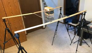
- A support system strong enough to suspend the plexiglass sheet high enough so you can photograph underneath the sheet.
- I use four camera tripods with two 6’ long 1”x2” boards for the plexiglass to rest on. Additional support material is needed based on object weight.
- A linear polarized ring flash with a circular polarizer on the lens.
A Ring Flash is Required
 A linear polarized ring flash with a circular polarizer on the lens. The ring flash will significantly reduce unwanted reflections. The polarization will reduce unwanted reflections and flare from the flash. The image on the left was captured from underneath the plexiglass using the room’s ambient light, showing reflections from the room that obscure the subject. The image on the right was captured from the same perspective, from underneath the plexiglass, but using the ringflash.
Caring for your Plexiglass
- Plexiglass scratches easily, so get an art portfolio bag or tape together a cardboard sleeve to protect your plexiglass.
- Don’t use Windex or any other kind of glass cleaner containing ammonia. Doing so will cause cracking in the plexiglass. A surface cleaning product like Brillianize, designed specifically for acrylic and similar materials, is required.
A Crucial Step
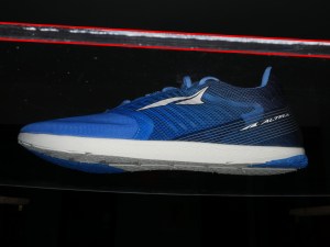
To successfully combine the sole with the top part of the shoe, capture overlapping images on all four sides, first from slightly above and then from slightly below the plexiglass. For the topside images, the camera lens is perpendicular to the object and just above the plexiglass sheet, its edge highlighted by the red lines in the right image. Below are a few images captured from this perspective.
Then capture images on the four sides of the plexiglass from just below the sheet, ensuring that the entirety of the object is visible through the plexiglass. In these images, the object will appear below the edge of the plexiglass, as shown in the image on the right with red lines highlighting the edge. Below are a few images captured in sequence from this perspective.
Processing Your Images
Software applications for processing photogrammetry range in cost, from free to thousands of dollars. Meshroom is a free, open source Windows and Linux platform that requires an NVIDIA CUDA enabled graphics card. The software has developed a strong following, though it does not allow for using measurement data and scaling models. Reality Capture by Capturing Reality is my preferred photogrammetry software because it’s significantly faster than other software available, but it only works on Windows with an NVIDIA CUDA enabled graphics card. Mac users are limited, primarily to Agisoft MetaShape, formerly known as PhotoScan. Compatible on both Mac and Windows, MetaShape is not GPU dependent. In 2014 I began doing photogrammetry with PhotoScan on a Macbook Air.
Here is a YouTube playlist of recommended video tutorials for the above mentioned software applications.
Processing your imagery connects the physical world with the digital world, opening up immersive experiential storytelling opportunities for informing and inspiring audiences. Photogrammetry makes this possible.
Journalism 360 is a global network of storytellers accelerating the understanding and production of immersive journalism. Our mission is to help news organizations, journalists, technologists, content creators and journalism educators experiment with all forms of immersive storytelling, including but not limited to 360 video, augmented reality, virtual reality and mixed reality.
This guide was created by the Online News Association with the support of the John S. and James L. Knight Foundation